Show Planes on Drawing Inventor
Cartoon dimensions are added to a cartoon to further document the model, without irresolute or controlling features or office size.
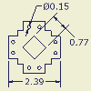
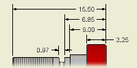
You add drawing dimensions every bit annotations to drawing views or geometry in drawing sketches. Drawing dimensions are expressed as numeric constants.
You tin add together text to a dimension. You can as well hide the dimension value and display the custom text instead.
Inspection dimensions are used during the quality control process. They are formatted specifically to indicate which dimensions must be checked before accepting a part. The dimension includes a label and an inspection rate.
Tip: Use the cartoon view context bill of fare to specify the note aeroplane and other dimension options.
Baseline dimensions
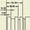
Baseline dimensions and baseline dimension sets automate adding multiple dimensions to drawing views. You specify an origin to calculate dimensions from, and select the geometry to dimension.
Notation: Spline endpoints are the but selectable points on a spline when you apply the baseline dimension control.
Ordinate dimensions
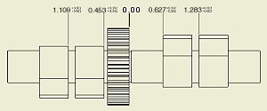
Use the Ordinate commands to add two types of ordinate dimensions to your drawings: ordinate dimension sets and individual ordinate dimensions. Individual ordinate dimensions provide support for imported AutoCAD drawings that contain ordinate dimensions.
The dimensions automatically align as you identify them. If dimension text overlaps, you tin can alter or create a dimension mode.
Apply a point, heart point, or directly edge as a location node for the Origin Indicator, or place the Origin Indicator anywhere inside the premises of the view.
Concatenation dimensions
Employ the Chain and Chain Set commands to add ii types of chain dimensions to your drawings: chain dimension sets and individual concatenation dimensions.
You select a base dimension for a chain. Then yous create dimensions which are parallel with the base of operations dimension. All selected dimensions get members of the chain. The dimensions are added from the 2d extension line of the selected base dimension in either direction.
Note: You can also select chain dimension set every bit base dimension, or equally additional dimension.
Foreshortened dimensions
Foreshortened dimensions reference an object (for example a work line or axis) that is exterior of a drawing view. After you place the foreshortened dimension, it is displayed even if you hide the out-of-view reference object.

Tip: Use commands in the context menu of a foreshortened dimension to customize the dimension advent, for example to hide the second arrowhead.
Dimensioning splines
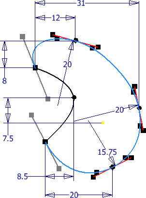
Dimensioning a spline presents unique challenges. Considering the shape is constantly irresolute, applying dimensions for annotation is less obvious than applying dimensions to a prismatic shape. To control the spline shape in the part model, dimensions are applied to fit points and curvature. The following paradigm shows a 2D spline sketch with dimensions on fit points and curvature.
You tin use the full general, baseline, and ordinate dimension commands to add dimensions to the endpoints of a spline. The General and Ordinate dimension commands can also apply dimensions to the X and Y Min/Max points of a spline. The Spline Min/Max snap setting is switched in the context menu. If it is off, y'all cannot add dimensions to the spline min/max points.
Notation: It is possible that the Spline endpoint could too be a Min or Max point. If this is the example, the endpoint takes priority.
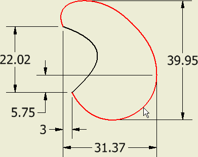
The following image shows full general dimensions applied to the X and Y minimum and maximum, and the endpoints of the highlighted spline.
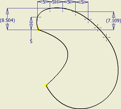
A useful technique y'all can use to dimension a spline anywhere forth the curve is to create a new sketch inside the drawing viewport containing the spline and project the spline geometry into the new sketch. You can then add together sketch points and dimension them at whatever point on the bend every bit shown in the following image. Utilize the recollect dimension command to make the sketch dimensions visible later you leave the sketch.
Yous can apply the Retrieve Dimension command in a cartoon to recover the dimensions practical to the spline in the model. Retrieved annotations cannot be located at critical dimension locations such as minimum and maximum width.
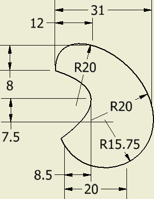
Using cartoon dimensions to annotate sketches
When you create a sketch in a drawing, yous use sketch dimensions to control its size. When yous finish the sketch, use Remember Dimensions to display the sketch dimensions on the sheet. The format is controlled by the agile dimension mode.
You lot can add cartoon dimensions as annotations to the geometry afterward closing the sketch. These dimensions are associated with the sketch and change when you motion or edit sketch geometry.
Note: Y'all can select drawing dimensions from the drawing sheet to a sketch using the Promote to Sketch office.
Dimensions in isometric views
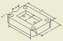
Yous can create dimensions in isometric drawing views. The dimension geometry (text, dimension lines, extension lines, leaders, arrowheads) is obliqued and aligned to the model geometry.
After yous select model edges or points, the dimension object is displayed and the corresponding aligned annotation planes are automatically inferred. Using the spacebar, you can toggle between inferred planes, or select the sheet airplane or a model work plane to place the dimension.
To select other than inferred annotation aeroplane, right-click and select:
Dimension Way
The dimension mode determines the default appearance and properties of dimensions in drawings. Information technology controls the dimension units and tolerances, display of dimension values, arrangement of dimensions in drawing views, manner and position of dimension texts, and properties of drawing notes.
Measurement Units
The dimension style determines the units of measurement for dimensions in drawings. If the units in the model are different than the units set in the style, dimensions in the cartoon are automatically converted to the units dictated by the style.
Copying dimension properties
Yous tin re-create i or more than properties from the selected dimension to a target dimension for all types of dimensions.
Notation: Individual ordinate and baseline dimension fix members are valid sources only, but the entire fix is a target.
Moving dimensions between views
You lot tin can move all types of dimensions between views of the aforementioned model on one canvas. Dimension attachment points must exist available in the target view.
Linear diametric dimensions deport as linear dimensions instead of diametric dimensions, so that a bore dimension created in the side view of a cylinder can be moved to the acme view of the cylinder. Diametric, radial, and athwart dimensions can simply be moved to a parallel view.
Notes:
- Yous can move dimensions for the following types of views:
- All orthographic base, projected, and auxiliary views. Views tin be rotated and alignment broken from the parent view.
- Item, section, and interruption-out views if attachment points are found in the view.
- Broken views, if an attachment indicate is available. If the attachment points are inside the break, the dimension is non visible. Removing the pause can make the moved dimension visible.
- You can move only dimensions attached to model geometry, and center lines or heart marks. The centerline or eye mark can be recovered from work features. The centerline or middle mark must be visible in both the parent and target views.
- You cannot move dimensions for the post-obit types of views:
- Draft views.
- Weldment views with unlike states, such as preparation and machining.
- Within one overlay view gear up.
- Canvass metallic folded views and sheet metallic flattened views of the same function.
- You cannot motion dimensions attached to sketch geometry, or moved to sketch geometry, except dimensions attached to recovered model sketches and 3D sketches. Dimensions attached to recovered model sketches can exist attached to the recovered sketch from the same model sketch in another view.
- Y'all cannot move dimensions if the move requires a change from a linear to a leadered dimension.
Arrange dimensions
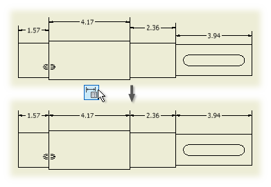
You tin can accommodate linear, angular, truthful isometric, and individual baseline and ordinate dimensions. Y'all can select one or multiple dimensions in one or multiple views.
You lot can select dimensions in the cartoon kickoff, and employ the Suit command. Alternatively, you tin click the Conform command first, and and so select the dimensions in the drawings.
mendozabillostrand.blogspot.com
Source: https://help.autodesk.com/cloudhelp/2020/ENU/Inventor-Help/files/GUID-438F8DED-72FA-460A-AB11-FBBD84194672.htm#!
0 Response to "Show Planes on Drawing Inventor"
Postar um comentário